

e are growing quickly here at Junction Networks, and part of this growth means we need to be able to handle more users. This is some thing we are all happy about! We have been tracking and forecasting our growth for some time so we can plan for our capacity needs in the future. To facilitate this capacity expansion, one of the main projects we've been working on is scaling our SIP proxy.
This is the first post of a multi post series all about scaling stateful sip proxy servers. Each post will try to cover an aspect of scaling.
Overview and enumeration of challenges
SIP Proxies
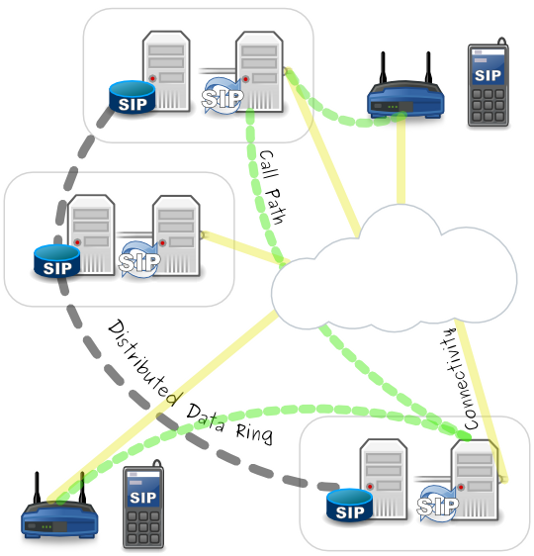
For those of you who don't know what a SIP Proxy is, you can think of it as the "Grand Central Terminal" of the network. SIP traffic is sent there and then gets sent out on its way to a different place. When someone calls you, a message is eventually sent to your SIP proxy. The SIP proxy knows where your phone is based on a location service, typically a sip registrar, so it relays the message down to your phone, then acts as an intermediary between you and the other caller until one of you hangs up. For a more explicit definition we turn to the core SIP specification.
RFC 3261
A proxy, or proxy server, "is an intermediary entity that acts as both a server and a client for the purpose of making requests on behalf of other clients. A proxy server primarily plays the role of routing, which means its job is to ensure that a request is sent to another entity "closer" to the targeted user. Proxies are also useful for enforcing policy (for example, making sure a user is allowed to make a call). A proxy interprets, and, if necessary, rewrites specific parts of a request message before forwarding it."
SIP Proxy servers can be of two general types: stateless, and stateful. Stateless SIP proxies don't know any contextual information about the messages they are receiving; they just forward things along without thinking about it where the message fits in a SIP transaction or dialog. Stateful SIP proxies keep track of what has happened in a call and use that information to make decisions about what to do throughout a call. The difference becomes important when you start talking about scaling.
Scaling
Scaling generally happens one of two ways in the software world: vertically, or horizontally. Vertical scaling means you buy bigger and bigger hardware to run the same software, thus giving you more resources to use. Horizontal scaling means you buy many of the same type of smaller hardware and distribute load. Each has it's advantages, but in the end, you can only vertically scale so far - to whatever the biggest computer in the world is. Generally speaking, horizontally scaling, while requiring more planning and initial time investment, can bring you nearly infinite growth capacity at a far lower cost ratio when compared to vertical scaling.
So, how do you how do you horizontally scale a sip proxy? Scaling stateful SIP proxies requires a lot more work than stateless proxies. This is because for any phone call, in a horizontally scaled architecture, it is very possible that messages will me exchanged between multiple SIP proxy servers. This requires that each server know about the exact same state information throughout the call.
Here are the main pieces of state that need to be distributed:
- User Location: What phones does a user have, and where are they located?
- NAT/Firewall traversal: What path must be followed to be able to get messages through a NAT/Firewall to a phone?
- Sequential Request Routing: If there are changes to this call: transfer, hold, etc. Where do those messages need to get sent in order to route back the same way the came?
There are several Request For Comments (RFC's) available that we have implemented to allow for the dissemination of this information between any number of stateful SIP proxy servers.
- Challenge 1 is solved by using a global view of registrations so that every SIP proxy has the same view of what phones are where.
- Challenge 2 is solved by using PATH headers (RFC 3327). PATH headers record the first server that received a request from a phone, the same one that will be keeping a NAT/Firewall open, and save it so that when we look up a users location, we know how to route the call back so that it will traverse a NAT/Firewall.
- Challenge 3 is solved by using GRUU's (RFC 5627) or Globally Routeable Useragent URI. During a call setup, each phone exchanges information on how it can be contacted for future requests. We change this contact and encode information so that the call can be globally routed from any where, solving a recurrence of issue 2).
Global View of User Location
This first challenge could be solved in many ways, but since we are talking about horizontal scaling here we need to keep in mind that any component that remains vertically scaled will eventually become a choke point and limit the ultimate scalability of all other horizontally scaled components. Our location storage mechanism has the following requirements:
- Horizontally scalable
- Readable from multiple locations
- Consistent view from any read location
- Writable from multiple locations
- Replicated for redundancy in a failure situation
For a long time while we were planning the SIP side of this scaling project, we had no idea what would fit these requirements. We literally called this storage mechanism “magic database.” After we switched gears to solve the data store problem we discovered a distributed database system called “Cassandra” that meets all these requirements, and provided us with some other cool features as well.
Cassandra Overview
Cassandra is a highly scalable second-generation distributed database based on Amazon Dynamo's fully distributed design and Google Bigtable's ColumnFamily-based data model. My guess is most people are thinking “what on earth does that mean?”
Cassandra is a non-relational data store. In the simplest terms it is a multi layer key value store. Here is an example of how we decided to structure our registration data within Cassandra:
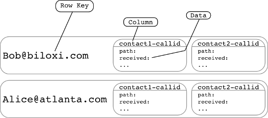
The most interesting thing about Cassandra is how it scales. Every time Cassandra receives a write from a client, such as a SIP Registrar, it will use a consistent hashing algorithm to create a token based on the “Row key” that you provide. This token can be anywhere from 0 to 2^127. Every Cassandra server or node that is part of the same ring is assigned an initial token which represents the starting point of the token space it is responsible for. Each node knows the token range that every other node has so that if it receives a write for a token it is not responsible for, it will send it off to the node that is responsible.
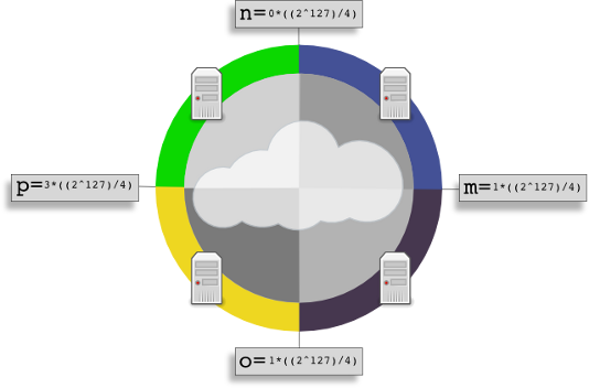
In the example image, each of four nodes has been given a evenly calculated initial token. This will make it so that writes are evenly distributed across the entire ring. Reads work in a similar fashion. Because each node knows about who is responsible for what token range, it can forward read requests to the proper node if it receives a read request for a token it is not responsible for. Cassandra also allows you to specify a replication factor so that when a write request is received, it will be replicated on the number of nodes you specify. For example, if you had a replication factor of 1, it would mean the primary write would go to the node responsible for the token, and a replicated write would go to another node chosen by a replication strategy.
NetworkTopologyStrategy Replication Strategy
Data availability is important, and that is where replication comes in. As noted above, Cassandra will automatically distribute data to each node based on the token calculated from the row key, but what about replicating that data to a different node so that it is backed up in case of a failure. Cassandra lets you pick a replication strategy that is basically an algorithm for how replica data is placed. We are talking about Network Topology Strategy because we have data centers in multiple locations, and we want to specifically place replicas so that each data center has a complete view of all registrations in the event of a failure.
Network Topology Strategy allows us to define data centers and racks in a topology file, this is what Cassandra refers to as a Snitch, or some thing that lets Cassandra know what nodes are where. An example property file snitch would be as follows:
10.0.0.1=DC1:RAC1
10.0.0.2=DC1:RAC2
10.0.1.1=DC2:RAC1
10.0.1.2=DC2:RAC2
This defines two data centers: DC1 and DC2, each with one node in each of two racks, RAC1 nad RAC2. When we specify a replication factor with Network Topology Strategy, we tell Cassandra how many, and where to put replicas.
replication_factor={DC1:1, DC2:1}
This will give each data center one replica copy of the data so that any one node can be lost and we still have access to all data. When one node goes down, Cassandra will automatically route requests to the node containing replica data.
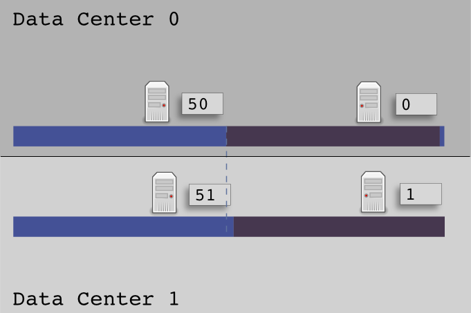
There are a few gotcha's that we have to be careful about when implementing Network Topology Strategy, primarily our initial token placement for nodes in data centers. Let me explain a little bit about how Cassandra places primary writes, and replicas before we talk about how to choose tokens.
For primary writes, Cassandra will write to the node whose Initial Token is closest without being larger then the data's token. When using Network Topology Strategy, Cassandra only has nodes in the remote data center to choose from when placing the replica, not the entire ring.
If we used the traditional sequential token ordering so that:
DC0R1:0, DC0R2:5, DC1R:10, DC1R2:15
A token of 3 would write to DC0R1, then replicate to the DC1R1. A token of 9 would write to the DC0R2 and replicate to DC1R1. Notice anything odd about this? Every replica from DC0 will always replicate to the node with the lowest start token in DC1 regardless of which node it landed on in DC0. Likewise, any replica from DC1 will replicate to the node with the highest token in DC0.
Offset Mirror Tokens can solve this uneven replication problem for us, and help to localize writes. To calculate offset mirrored tokens we must calculate nodes in each data center as if they were the entire ring.
The formula to calculate the ideal Initial Tokens is:
Initial_Token = Zero_Indexed_Node_Number * ((2^127) / Number_Of_Nodes)
For the first node in the first data center (N0DC0):
Initial token = 0 * ((2^127) / 2)
Initial token = 0
For the second node in the first data center (N1DC0):
Initial token = 1 * ((2^127) / 2)
initial token = 85070591730234615865843651857942052864
Now, for the second data center do the exact same process, but no two nodes can have the same token so offset the tokens by adding 1 to the token value.
For the first node in the second data center (N0DC1):
initial token = 1
For the second node in the second data center (N1DC1):
initial token = 85070591730234615865843651857942052865
Now when Cassandra receives a write request to a node in DC0, it has the entire token range available between the two nodes, so it can keep the write local to DC0, then when it does the replica write to DC1, it will mirror the data because DC1 nodes have the exact same token ranges, off set by one. This will create an even distribution of initial writes and replica data, giving us the availability that we need for global user location data storage. I know this post has not been a whole lot about SIP or VoIP, but it is about critical infrastructure that we rely on to provide SIP based location services, which I will cover more in my next post: Path headers, and Home Proxies.